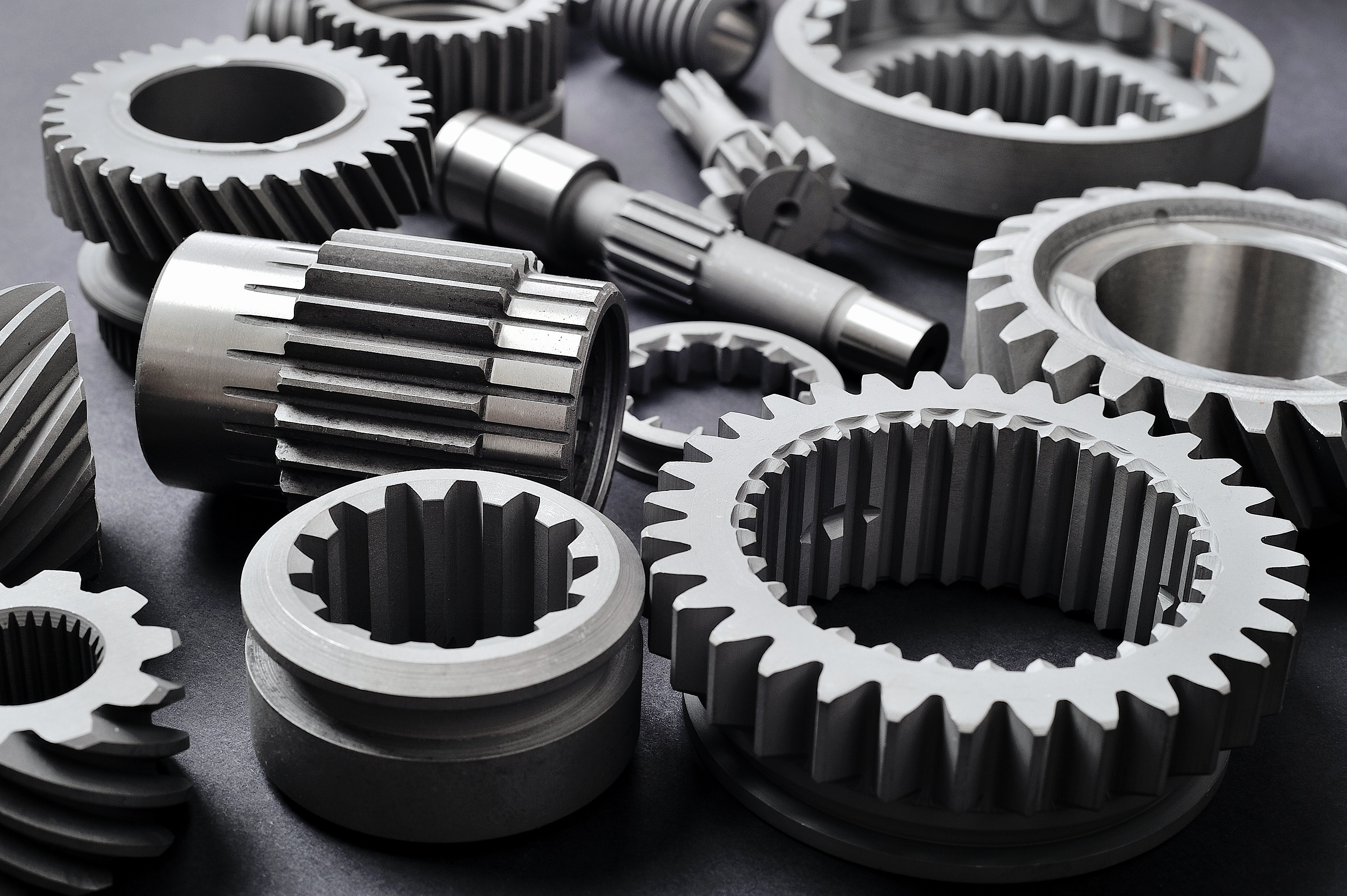
Parts with complicated shapes have certain test areas that are difficult or impossible to access with eddy current probes. Often, the only remaining method for crack detection was magnetic particle inspection. With induction thermography, FOERSTER now offers a new, automatable solution for component testing. This method is suitable for the examination of semi-finished products as well as complexly shaped components.
Induction thermography allows for a contact-free crack detection on metallic components with complex geometries. A current induced into the workpiece generates localized hotspots at the defects in the material. These hotspots can be detected through their heat radiation with an infrared camera.


Induction thermography is a non-destructive and contact-free procedure for the detection of surface cracks on conductive materials. The eddy currents produced by an induction coil are locally distorted by cracks in the material surface. Accordingly, temperature surges - so-called hotspots - occur in the corresponding positions. With the help of a thermal imaging camera, defects are thus made visible.
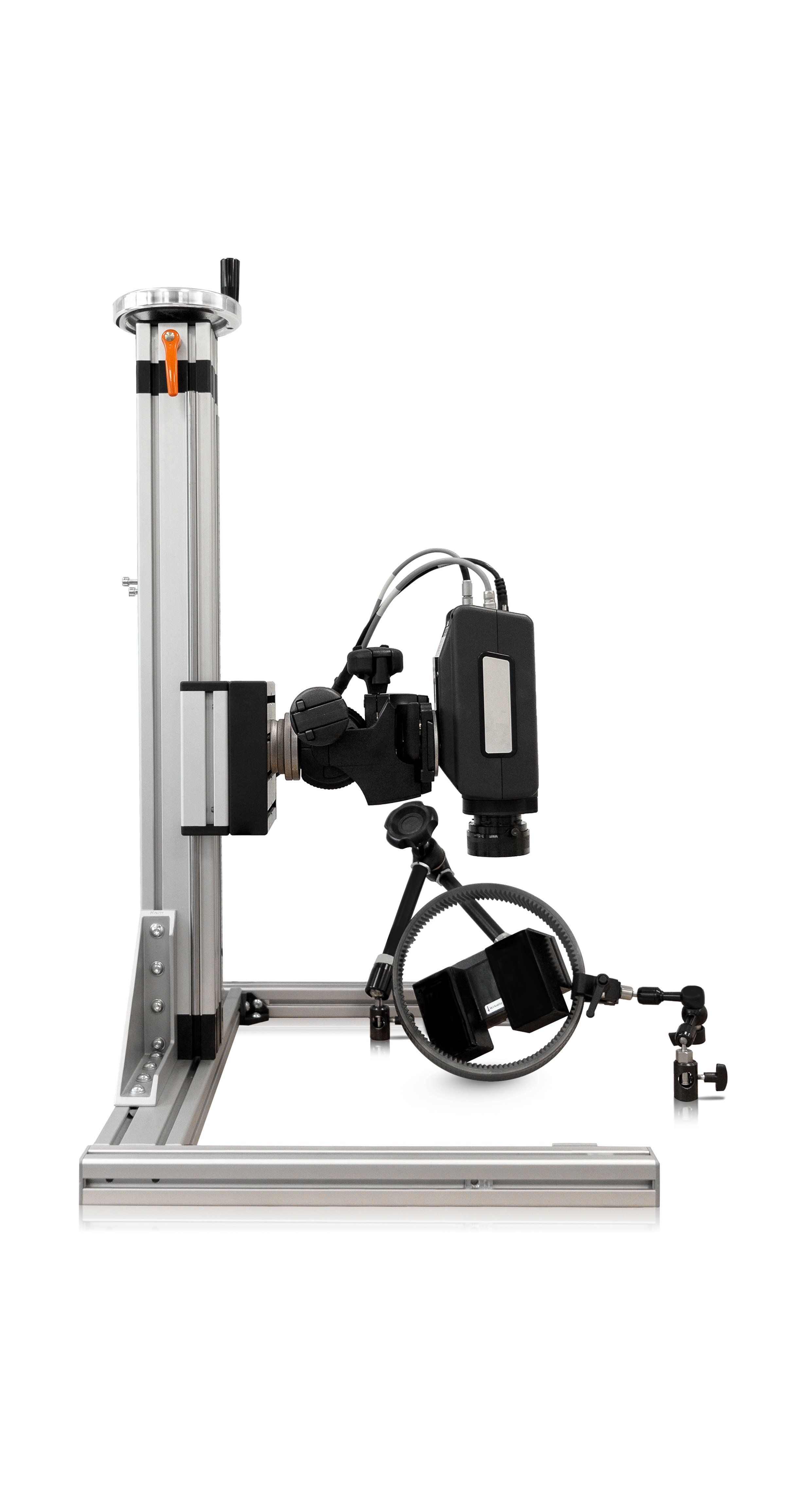
A typical system consists of an infrared camera, an inductor (see figure right) including a generator for high-power pulses (without illustration). The inductor is positioned such that a magnetic field pulse induces currents in the test area, heating the part by a few degrees Celsius. Simultaneously the camera is recording the same area. The camera captures the heat radiation, which is emitted as infrared light, and creates a temperature image of the surface.

Pinion in infrared camera
The surface temperature can be seen in the infrared spectral range. Without external thermal excitation, only the geometry of the component is shown.
%20%5BIntensit%C3%A4t%20(DL)%5D%20(141).png)
%20%5BPhase%20(%C2%B0)%5D%20(5%2c000Hz)_retouched.png)

Pinion with induction
thermography
A crack is visible in the gear root. Cracks are particularly heated by induction. This creates hotspots that form like strings of pearls.

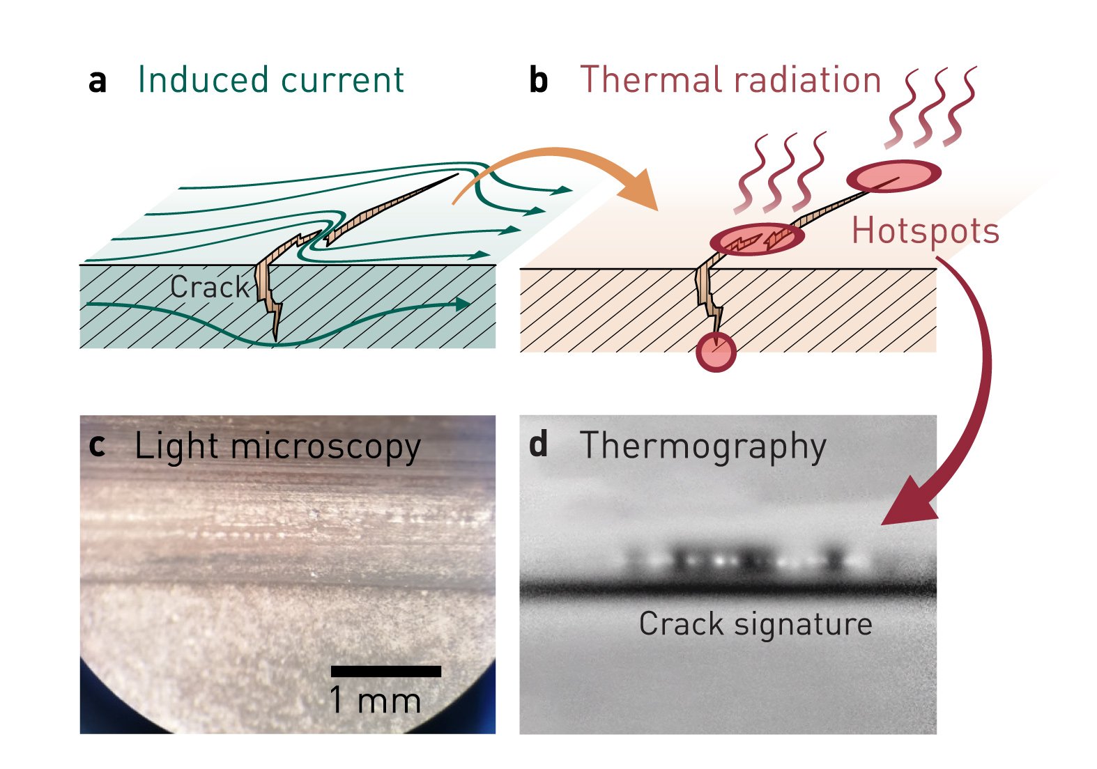
If there are defects (e.g. cracks) in the test area, the induced current is deviated and is locally displaced or squeezed (a). Consequently, those locations in the part are heated stronger (b). When such hotspots form directly at the surface, they emit heat radiation and are visible to the camera. The heat from hotspots within the material can also reach the surface through the heat conduction of the material. However, the range into the material is limited by the penetration depth of the induction.
The thermal recordings are analyzed with video and image processing algorithms. On a thermography recording (d), the hotspots leave a crack signature similar to a string of pearls. In contrast, other surface features, such as roughness and scratches, are suppressed. This way cracks can be detected that would be difficult or impossible to distinguish in a conventional photo (compare c). The high contrast and characteristic shape of cracks in induction thermography images allows for reliable algorithmic detection and enables the full automation of the procedure right up to a sorting result.

Sintered parts
Turbine blades

Under certain circumstances, internal gear profiles are also accessible.

Hardening cracks running along the circumference can be efficiently detected.

Cracks that occur on the bends can be detected. However, thermography cannot efficiently cover large test areas.

Cracks, pores and incomplete fusions are visible with minimal interference.

Creases on the parts are particularly prone to crack. Such defects are accessible with thermography. However, very deep creases may also pose a challenge for this method.

Thermography is suitable for cutting-edge materials and flexible enough to handle very complex geometries.
140 Industry Dr,
Pittsburgh PA,
15275